- 您现在的位置:买卖IC网 > Sheet目录869 > MP028T036M12AL (Vicor Corporation)MIL-COTS PRM REGULATOR
�� �
�
�MP028F036M12AL�
�Application� Information� (continued)�
�OVP� –� Overvoltage� Protection�
�The� output� Overvoltage� Protection� set� point� of� the� MP028F036M12AL�
�is� factory� preset� for� 55� V.� If� this� threshold� is� exceeded� the� output� shuts�
�down� and� a� restart� sequence� is� initiated,� also� indicated� by� PC� pulsing.�
�If� the� condition� that� causes� OVP� is� still� present,� the� unit� will� again� shut�
�down.� This� cycle� will� be� repeated� until� the� fault� condition� is� removed.�
�The� OVP� set� point� may� be� set� at� the� factory� to� meet� unique� high�
�Adjusting� Current� Limit�
�The� current� limit� can� be� lowered� by� placing� an� external� resistor�
�between� the� I� L� and� SG� ports� (see� Figure� 20� for� resistor� values)� .� With�
�the� I� L� port� open-circuit,� the� current� limit� is� preset� to� be� within� the�
�range� specified� in� the� output� specifications� table� on� Page� 4.�
�voltage� requirements.�
�1000�
�22uF� (ESR� >=� 1.7Ω)� &� 33uf� (ESR>=� 1.35Ω)� &� 47uF� (ESR� >=� 1.1Ω)� -� NO� IL� TRIM�
�10uF (ESR >= 2.40Ω)�
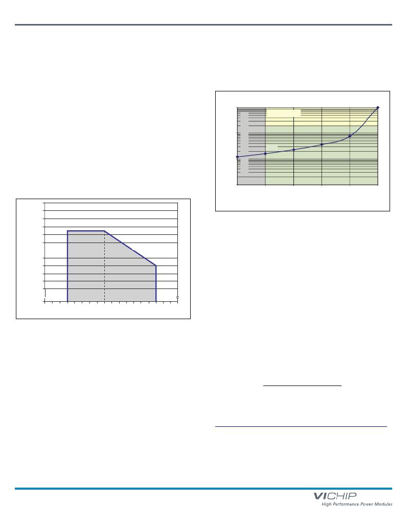
�PRM� Output� Power� Versus� VTM� Output� Power�
�As� shown� in� Figure� 19,� the� MP028F036M12AL� is� rated� to� deliver� 3.3� A�
�maximum,� when� it� is� delivering� an� output� voltage� in� the� range� from�
�26� V� to� 36� V,� and� 120� W,� maximum,� when� delivering� an� output�
�voltage� in� the� range� from� 36� V� to� 55� V.� When� configuring� a� PRM� for�
�use� with� a� specific� VTM,� refer� to� the� appropriate� VTM� data� sheet.� The�
�VTM� input� power� can� be� calculated� by� dividing� the� VTM� output� power�
�by� the� VTM� efficiency� (available� from� the� VTM� data� sheet).� The� input�
�100�
�10�
�0uF�
�power� required� by� the� VTM� should� not� exceed� the� output� power� rating�
�of� the� PRM.�
�1�
�75%�
�80%�
�85%�
�90%�
�95%�
�100%�
�4.00�
�3.80�
�3.60�
�3.40�
�3.20�
�%� Percentage� of� Current� Limit� Setpoint�
�Figure� 20� —� R� IL� vs� percentage� of� current� limit.� Shaded� areas� shown�
�minimum� valid� R� IL� as� a� function� of� load� capacitance� and� ESR.�
�3.00�
�2.80�
�2.60�
�2.40�
�2.20�
�2.00�
�1.80�
�Safe� Operating�
�Area�
�-� 0.066� A� /� V�
�Input� Fuse� Recommendations�
�A� fuse� should� be� incorporated� at� the� input� to� the� PRM,� in� series� with�
�the� +In� port.� A� fast� acting� fuse,� NANO2� FUSE� 451/453� Series� 10� A�
�125� V,� or� equivalent,� may� be� required� to� meet� certain� safety� agency�
�Conditions� of� Acceptability.� Always� ascertain� and� observe� the� safety,�
�regulatory,� or� other� agency� specifications� that� apply� to� your� specific�
�application.�
�0�
�~� ~�
�20� 22�
�24� 26�
�28� 30�
�32� 34�
�36� 38�
�40� 42�
�44� 46�
�48� 50�
�52� 54� 56�
�Product� Safety� Considerations�
�Factorized� Bus� Voltage� (V� F� )�
�Figure� 19� —� MP028F036M12AL� rating� based� on� Factorized� Bus� voltage�
�The� Factorized� Bus� voltage� should� not� exceed� an� absolute� limit� of�
�55� V,� including� steady� state,� ripple� and� transient� conditions.� Exceeding�
�this� limit� may� cause� the� internal� OVP� set� point� to� be� exceeded.�
�If� the� input� of� the� PRM� is� connected� to� SELV� or� ELV� circuits,� the� output�
�of� the� PRM� can� be� considered� SELV� or� ELV� respectively.�
�If� the� input� of� the� PRM� is� connected� to� a� centralized� DC� power� system�
�where� the� working� or� float� voltage� is� above� SELV,� but� less� than� or�
�equal� to� 75� V,� the� input� and� output� voltage� of� the� PRM� should� be�
�classified� as� a� TNV-2� circuit� and� spaced� 1.3� mm� from� SELV� circuitry� or�
�accessible� conductive� parts� according� to� the� requirements� of�
�UL60950-1,� CSA� 22.2� 60950-1,� EN60950-1,� and� IEC60950-1.�
�Parallel� Considerations�
�The� PR� port� is� used� to� connect� two� PRMs� in� parallel� to� form� a� higher�
�power� array.� When� configuring� arrays,� PR� port� interconnection�
�terminating� impedance� is� 10� k� to� SG.� See� note� Page� 8� and� refer� to�
�Application� Note� AN002.� Additionally� one� PRM� should� be� designated�
�as� the� master� while� all� other� PRMs� are� set� as� slaves� by� shorting� their�
�SC� pin� to� SG.� The� PC� pins� must� be� directly� connected� (no� diodes)� to�
�assure� a� uniform� start� up� sequence.� Consult� Vicor� applications�
�engineering� for� applications� requiring� more� than� two� PRMs.�
�Application� Notes�
�For� PRM� and� VI� Chip� ?� application� notes� on� soldering,� board� layout,�
�and� system� design� please� click� on� the� link� below:�
�http://www.vicorpower.com/technical_library/application_information/chips /�
�Applications� Assistance�
�Please� contact� Vicor� Applications� Engineering� for� assistance,�
�1-800-927-9474,� or� email� at� apps@vicorpower.com.�
�PRM� ?� Regulator� 28� Vdc� Input�
�Page� 10� of� 14�
�Rev� 3.5�
�1/2013�
�vicorpower.com�
�800� 735.6200�
�发布紧急采购,3分钟左右您将得到回复。
相关PDF资料
MPD6S022S
CONV DC/DC 3A 3-5.5VIN 95% EFF
MPDRX312S
CONV DC/DC 16A 3-5.5VIN HI-SPEED
MPDTY026S
CONV DC/DC 15W 2.5VOUT 6A SIP
MPDTY116S
CONV DC/DC 15W 2.5VOUT 6A SMT
MPDTY201S
CONV DC/DC 3A 3-5.5VIN
MPXQP47K
CAP FILM 0.47UF 275VAC RADIAL
MPZ1608Y101B
FERRITE CHIP 100 OHM 2A 0603
MS1-AA-PC
CONTACT BATTERY AA POS/NEG
相关代理商/技术参数
MP02S
制造商:CHENG-YI 制造商全称:CHENG-YI ELECTRONIC CO., LTD. 功能描述:15/25/35 AMPS. SILICON BRIDGE RECTIFIERS
MP02TT200
制造商:DYNEX 制造商全称:Dynex Semiconductor 功能描述:Dual Thyristor Water Cooled Module Preliminary Information
MP02TT200-12
制造商:DYNEX 制造商全称:Dynex Semiconductor 功能描述:Dual Thyristor Water Cooled Module Preliminary Information
MP02TT200-13
制造商:DYNEX 制造商全称:Dynex Semiconductor 功能描述:Dual Thyristor Water Cooled Module Preliminary Information
MP02TT200-14
制造商:DYNEX 制造商全称:Dynex Semiconductor 功能描述:Dual Thyristor Water Cooled Module Preliminary Information
MP02TT200-15
制造商:DYNEX 制造商全称:Dynex Semiconductor 功能描述:Dual Thyristor Water Cooled Module Preliminary Information
MP02TT200-16
制造商:DYNEX 制造商全称:Dynex Semiconductor 功能描述:Dual Thyristor Water Cooled Module Preliminary Information
MP02TT800
制造商:DYNEX 制造商全称:Dynex Semiconductor 功能描述:Dual Thyristor Water Cooled Welding Module Preliminary Information